CAD Design and Planning
Inspiration kinda started all the way back to when I was a kid visiting a relative's house that had four old Yamaha and Suzuki dirt bikes. My great Uncle at the time was an airplane mechanic and taught me all about the motorcycles. Cut to about a year ago building my motorized bicycle that I found out about a company called Motoped. They build bicycle/dirt bike hybrids but were too expensive for me. I needed something that I could ride around college, something small that would work with bike racks and wouldn't disturb people on walkways with a quiet electric motor but could also be easily swapped out with a gas engine with just a chain and a couple bolts being changed. I spent months on the CAD model, figuring out the dimensions, what I could and couldn't make with the materials and tools I had, and keeping cost down and making it so I could build the entire bike within the end of the school year and leave room for future improvement.


Getting/Making parts
Many parts came from a Craigslist bike that I purchased for only $200. It had nice wheels, front fork, rear shock and pedals and chain etc, it was going to save me a lot of time and money down the road. Both the front and rear rims were either bent and or loose which would cause a couple headaches later, but I wasn't worried about that yet before the motorcycle even existed.


Custom Designed, 3D Printed and Wrapped Brushless 3 Phase Electric Motor
This is where most of my research and energy went into. After being in the hobby of remote control cars and quadcopters for a while and reading a lot of articles online, I felt ready to design my own brushless motor capable of generating 10kW or more of power... I could make the face plates and wrap it etc but how was I going to make a custom stator without breaking the bank with a custom one-off from a third party source? There was someone I saw earlier on YouTube who 3D printed their own Halbach array motor which generated 600 watts, pretty good but ProtoPasta makes ferromagnetic PLA filament with iron particles mixed with the plastic... I looked around and it appeared to me that no one had every experimented with how iron filament effects the strength and efficiency as compared to other kinds of plastic and metal-infused PLA. I printed samples from my stator design with 2 teeth, printed each one in plain PLA, iron PLA, carbon conductive PLA, a mix of conductive and iron PLA switching each layer, and a mix of conductive and regular PLA switching each layer. Each sample was wrapped 20 times on each tooth with a single strand of 20AWG wire and hooked up to a 12v lead acid battery for a few seconds while the magnetometer in my phone measured the strength of the magnetic field.


Results:
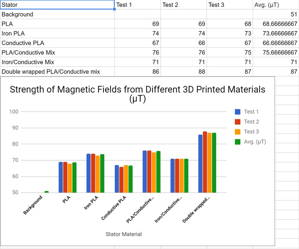
It appears that the PLA/Conductive mix won out, but I chose to go ahead with the Iron PLA because it's the Iron that makes the plastic more permeable to magnetic fields and was the cheaper option in the end. From here, time to print a stator completely out of iron-PLA with 48 teeth and 24 magnetic poles.
Printing and Wrapping the Motor + Testing
First hurdle was the print the stator, but since the Iron filament was brittle and had a tendency to get clogged, I had to print the stator in 5 thinner slices and glue it together with super glue. Once that was done, it was wrapped with 13 strands of 24AWG copper wire in 4 turns per tooth (which in hindsight wasn't enough to handle the current) by hand in a vice. The plates were water jet cut from 1/4in aluminum and the rotor was a sandwich of 1/4in aluminum and a plastic magnet holder/spacer. Neodymium N35 magnets were epoxied on and covered with a kevlar and carbon fiber epoxy wrap.


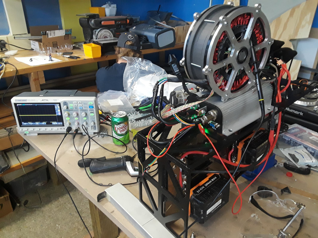
Controlling and Testing the Motor
The motor now needed a power source and something to control it, so I chose to use a 220amp sensored Kelly motor controller running off of 20v Porter Cable drill batteries. I wired up 3 Hall sensors for the speed controller to use for rotor positioning and tested it up to 5000 rpms before I stopped out of worry it was going to explode.


Making the Frame


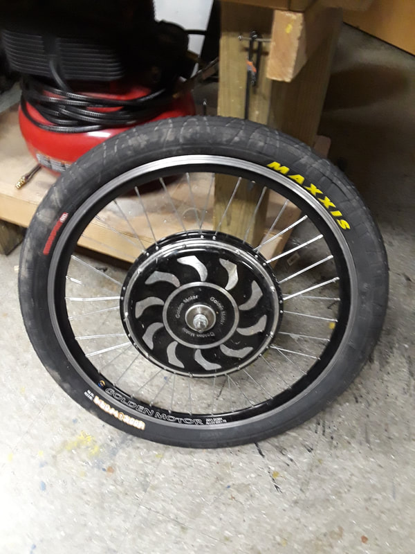
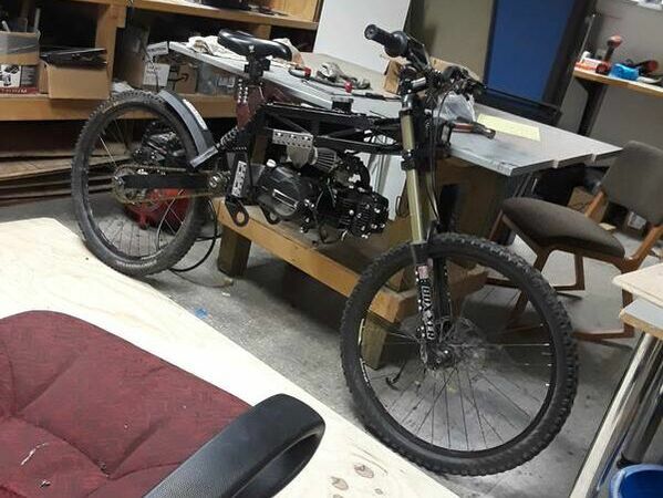
Installing the 80cc gas engine and new Maxxis tires


Motor V3: Epoxy + iron powder + new tooth design
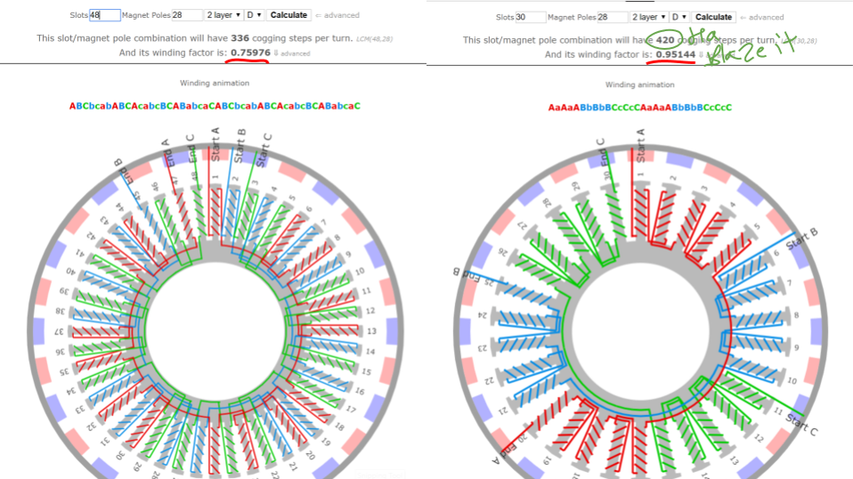
The PLA and iron stator wasn't going to last long, is was plagued by a couple problems: PLA's glass transition temperature is around 60 degrees C meaning that when the motor gets just above warm, the stator becomes soft and wobbly. Also, its tooth to pole ratio of 48:28 actually is only 76% efficient on paper. And finally, the stator only had about 11% iron in its core, leading to poor channeling of the magnetic field to the surface of the teeth. With this new motor stator, it will be a 3D printed casting of electronic potting epoxy (low conductivity, high heat conductivity) and iron powder with 30 teeth instead to increase its efficiency to 95%. To make this new stator, I had to redesign the stator to have 30 teeth, print it in iron PLA but only 1 layer thick, find the optimal epoxy and iron powder ratio for mold pouring, and get everything to set correctly for the gap within the stator to still have an air gap with the rotor of under 1mm. After a quick redesign, I first set out to find the most iron powder I can mix into epoxy while still being good for pouring into a complex mold. The iron powder I was using was soft 99.5% pure 100 mesh iron powder from chemicalstore.com and the epoxy was a potting epoxy for electronics with a very low electrical conductivity and high heat conductivity, perfect for preventing eddy currents throughout the stator and conducting heat away from the stator teeth. After trying 1:2, 1:1 and 3:2 ratios of iron:epoxy, I found that 3:2 was the upper limit with the mixture having the viscosity of watery mashed potatoes and could be poured if I was patient enough. This mixture in a stator would mean I have 60% iron over the last version having only 11%. After finding my mixing ratio, I placed the samples in the oven at 100 degrees C for a couple minutes at first and found that they retained their shape even when in a PLA mold. Then I left them in the oven for an hour and still no ill-effects. The mold samples came out rubbery, but didn't permanently deform under my stretching and squeezing, so not perfect but much better than the last stator even under lower temperatures. Next a mold was printed out of iron PLA (the leftover from the last stator, and because I wanted to increase the iron content as much as possible) one layer thick, a new cup of iron epoxy mashed potatoes was whipped up and, more pushed into the stator rather than poured. It was very messy but it set over the next couple days, and left me with an intact, windable stator with enough clearance for the rotor to spin smoothly, so then it was on to the winding. Since my last motor got hot just under a couple minutes around 30 amps, this motor will have more wires that are thicker with the same amount of turns. The last stator had 4 turns per tooth of 13 strands of 24AWG wire. This new stator has 4 turns per tooth of 16 strands of 22 AWG wire which has really taken a toll on my hands from winding.


V3 Motor swap and testing


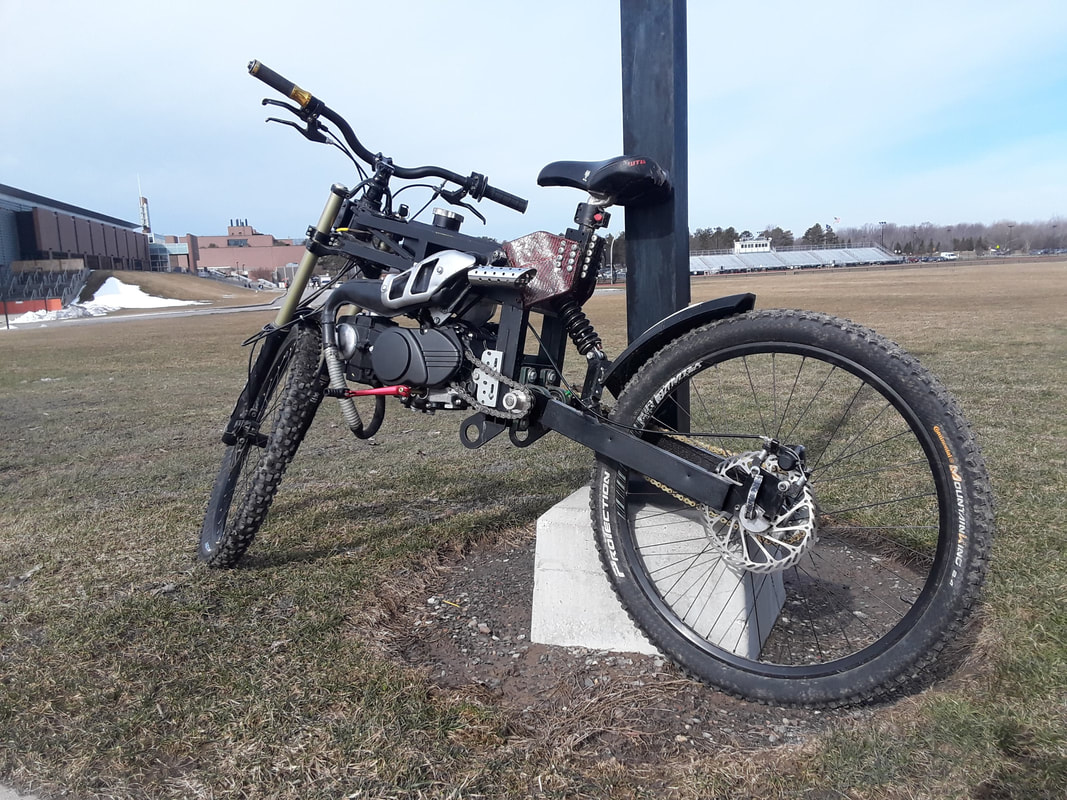
New rear arms and drive train
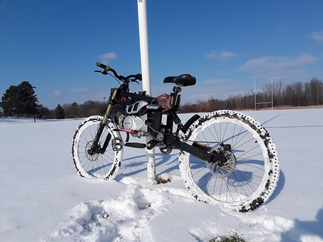
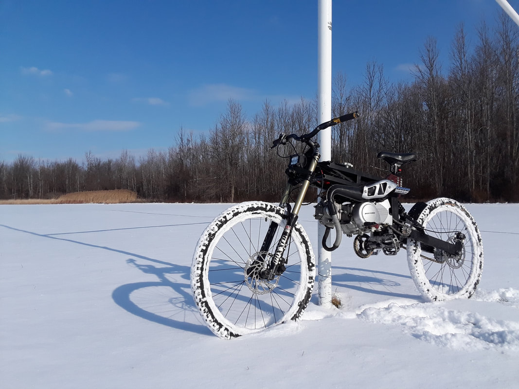
So my original aluminum arms weren't going to cut it. They were too flexible and could scissor, causing the rear wheel to easily canter left and right, making the bike feel very unstable and shaky. After looking at rear arm designs from Motoped and dirtbikes, I designed a longer, stiffer arrangement out of steel tubing. This new design also gets rid of the derailleur and bike chain as well as the cassette which had the tendency to skip under higher load and I didn't want to break a chain in the middle of the road or woods, miles away from home. New steel arms were cut out of old bed frames, 1/4in plate with a waterjet, and welded together at an alumni's house. This new rear arm increased the stiffness of the rear suspension by moving the loading point up an inch giving the shock absorber a great moment on the arms and the stiffer welds (as supposed to screws) on the rear arm made the rear wheel move a couple inches back as well as not flex as much as the aluminum. In this time I was also experimenting with attaching a snowmobile ski to the front for snow use, which I then put the original front tire back on. The ski will come back once there's more snow on the ground and I upgrade the engine from 80cc to hopefully 125 or 140cc for a little more kick.
Click on each photo for more info.
Click on each photo for more info.


New 125cc Engine and engine mount


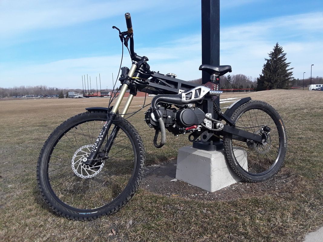
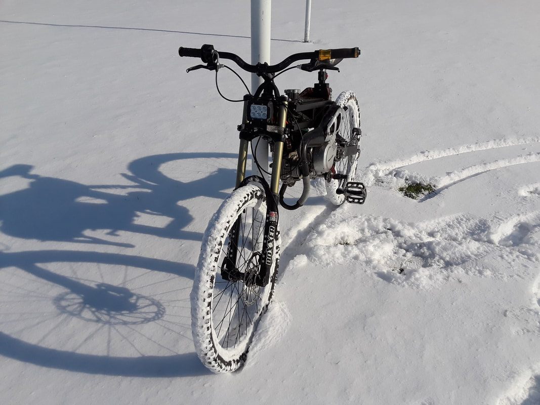
Gas version finished!
Coming Soon...